

No products in the cart.
Arduino ESPLORA Joystick Photosensitive Sensor Board, Support LCD

Roll over image to zoom in
₹2,430.00₹2,999.00 (-19%)
Arduino’s brand-new Esplora microcontroller, packed with prebuilt sensors and features, could indicate a move for the DIY electronics company toward a wider segment of the microcontroller market.
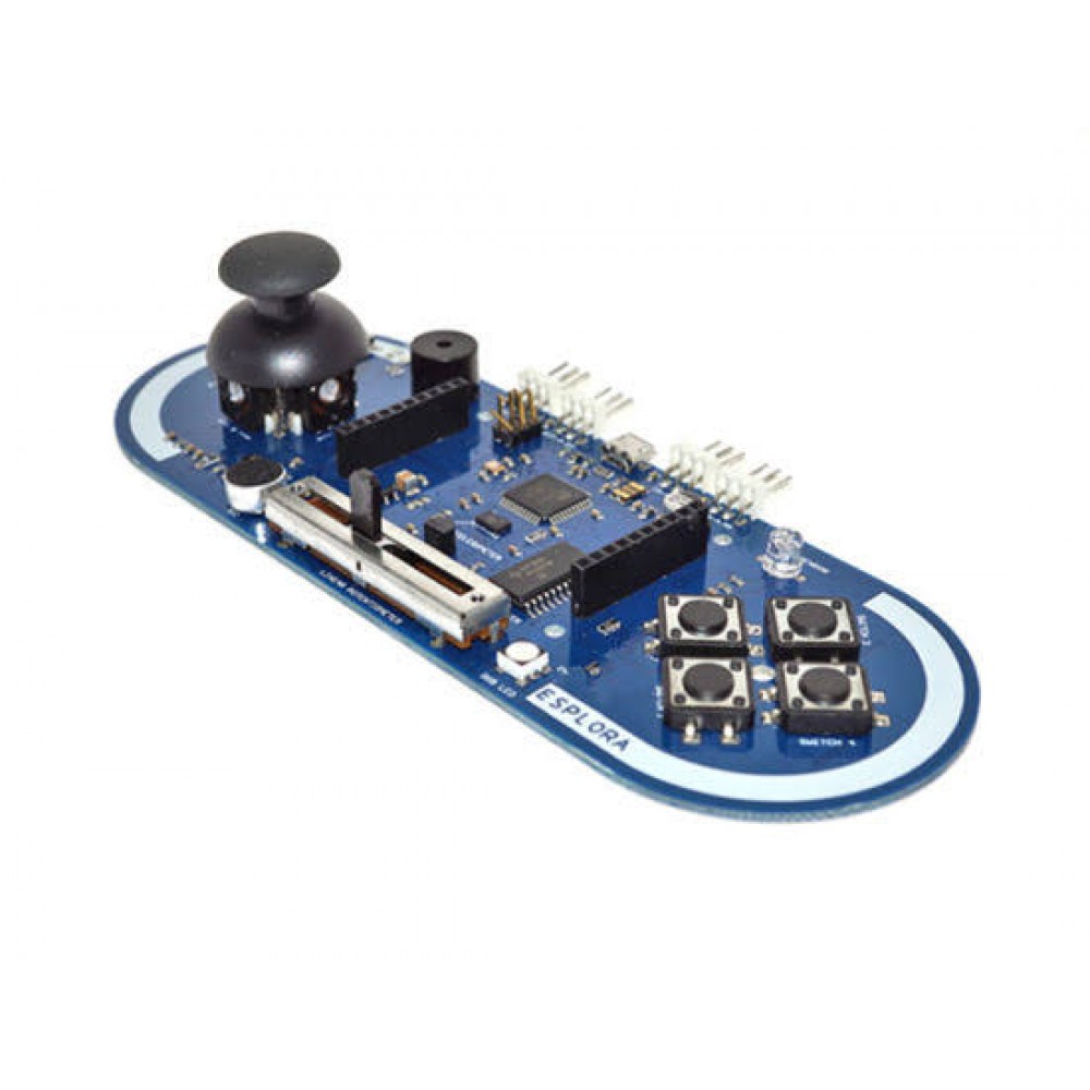
Esplora looks like the innards of a video game controller — it even features push-buttons and an analog joystick. But although it is preprogrammed with a game-controller script, it’s not just for gaming. It also incorporates sound, light, and temperature sensors — all run through an analog multiplexer — as well as a three-axis accelerometer.
The board contains everything need to support the microcontroller; simply connect it to a computer with a USB cable to get started. The Esplora has built-in USB communication; it can appear to a connected computer as a mouse or keyboard, in addition to a virtual (CDC) serial / COM port. This has other implications for the behavior of the board; these are detailed on the getting started page. You can find all the information you need to configure your board, use the Arduino Software (IDE); and start to tinker with coding and electronics.
Memory:
The ATmega32u4 has 32 KB (with 4 KB used for the bootloader). It also has 2.5 KB of SRAM and 1 KB of EEPROM (which can be read and written with the EEPROM library).
Input and Output:
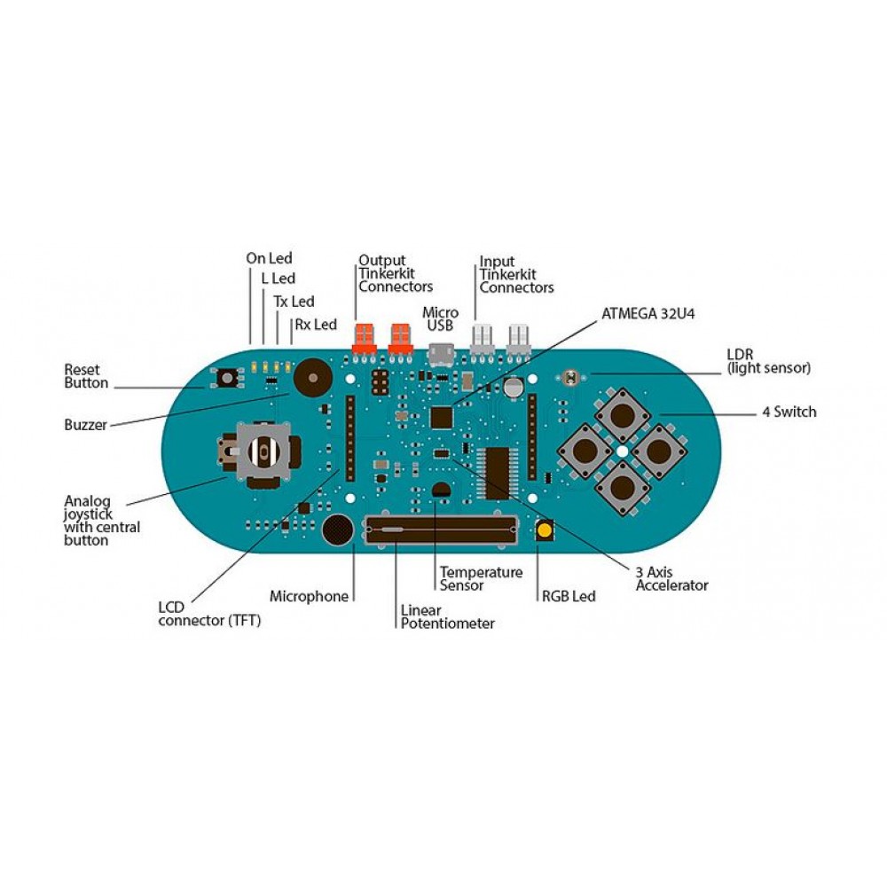
The design of the Esplora board recalls traditional gamepad design with the analog joystick on the left and four push buttons on the right. The Esplora has the following onboard inputs and outputs :
- Analogue joystick with central push-button two axis (X and Y) and a centre pushbutton.
- 4 push-buttons laid out in a diamond pattern.
- Linear potentiometer slider near the bottom of the board.
- Microphone for getting the loudness (amplitude) of the surrounding environment.
- Light sensor for getting the ambient brightness.
- Temperature sensor reads the ambient temperature (please note that the temperature sensor is not fitted, however we do stock this component).
- Three-axis accelerometer measures the board's relation to gravity on three axes (X, Y, and Z)
- Buzzer can produce square-waves.
- RGB led bright LED with Red Green and Blue elements for colour mixing.
- 2 TinkerKit Inputs to connect the TinkerKit sensor modules with the 3-pin connectors.
- 2 TinkerKit Outputs to connect the TinkerKit actuator modules with the 3-pin connectors.
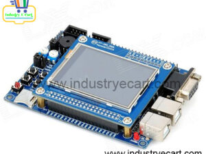
- TFT display connector connector for an optional color LCD screen, SD card, or other devices that use the SPI protocol.
- In order to utilise the total number of available sensors, the board uses an analogue multiplexer. This means a single analog input of the microcontroller is shared among all the input channels (except the 3-axis accelerometer). Four additional microcontroller pins choose which channel to read.
Communication :
The Leonardo the Arduino ESPLORA Joystick Photosensitive Sensor Board has a number of facilities for communicating with a computer; another Arduino, or other micro-controllers. The ATmega32U4 provides serial (CDC) communication over USB and appears as a virtual com port software on the computer. The chip also acts as a full speed USB 2.0 device, using standard USB COM drivers. On Windows, a .inf file requires.
The Arduino software includes a serial monitor which allows simple textual data to be sent to and from the Arduino board. The RX and TX LEDs on the board will flash when data is transmitting via the USB connection to the computer. The ATmega32U4 also supports SPI communication, that access through the SPI library. The Esplora can appear as a generic keyboard and mouse and can be a program to control these input devices using the Keyboard and Mouse libraries.
Programming :
The Esplora can be the program with the Arduino software (download). Select “Arduino Esplora” from the Tools > Board menu. For details, see the getting started page. The ATmega32U4 on the Arduino Esplora comes pre-burn with a boot-loader that allows you to upload new code to it without the use of an external hardware programmer.
It communicates using the AVR109 protocol. You can also bypass the bootloader and program the microcontroller through the ICSP (In-Circuit Serial Programming) header; see these instructions for details.
To facilitate writing sketches for the Esplora; there is a dedicated library that contains methods for reading the sensors and writing to the outputs onboard. The library offers high-level methods which provide pre-process data, like degrees Fahrenheit or Celsius from the temperature sensor. It also enables easy access to the outputs, like writing values to the RGB LED.
Automatic (Software) Reset and Bootloader initiation :
Rather than requiring a physical press of the reset button before an upload; the Esplora is designing in a way that allows it to be reset by software running on a connected computer. The reset is trigger when the Esplora’s virtual (CDC) serial / COM port is open at 1200 baud and then close. When this happens, the processor will reset, breaking the USB connection to the computer (meaning that the virtual serial / COM port will disappear). After the processor resets, the boot-loader starts, remaining active for about 8 seconds. The boot-loader can also be initiate by pressing the reset button on the Esplora.
Note that when the board first powers up, it will jump straight to the user sketch; if present, rather than initiating the boot-loader. Because of the way the Esplora handles reset it’s best to let the Arduino software try to initiate the reset before uploading; especially if you are in the habit of pressing the reset button before uploading on other boards. If the software can’t reset the board you can always start the boot-loader by pressing the reset button on the board.
USB Overcurrent Protection :
The Esplora has a re-settable poly-fuse that protects your computer’s USB ports from shorts and over-current. Although most computers provide their own internal protection, the fuse provides an extra layer of protection. If more than 500 mA is applied to the USB port, the fuse will automatically break the connection until the short or overload is removed.
Physical Characteristics :
The maximum length and width of the Esplora PCB are 6.5 and 2.4 inches respectively, with the USB and TinkerKit connectors extending beyond the latter dimension. Four screw holes allow the board to be attached to a surface or case.
Package Includes :
1 x Arduino ESPLORA Joystick Photosensitive Sensor Board.
Reviews
There are no reviews yet.